The tag does not transmit. It changes the echo.
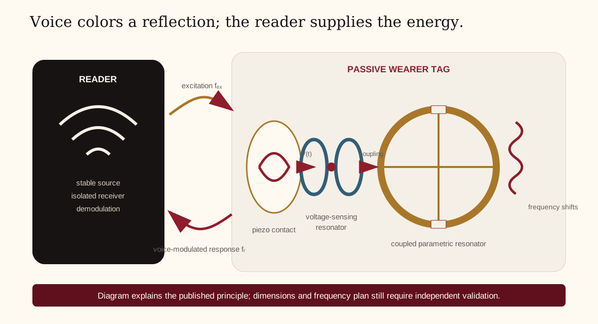
A reader supplies electromagnetic energy. Voice-induced sensor voltage changes a resonant or reflective property. The reader observes that tiny change beside a vastly larger self-signal.
Historical mechanism
In 1945 Soviet schoolchildren presented a carved Great Seal to US Ambassador Averell Harriman. The passive device inside was found in 1952. The NSA describes external radio illumination and diaphragm motion changing the resonant return. This corrects the common retelling: it was Soviet intelligence against the US mission in Moscow, not a Mossad gift to the CIA. NSA National Cryptologic Museum.
Modern feasibility anchor: TagMic
Wang et al. report a fully batteryless wireless microphone in 2025. Their tag couples a passive piezoelectric sensor into a voltage-sensing resonator (VSR), which shifts with varactor capacitance; a coupled parametric resonator (PR) produces a frequency-separated response. The laboratory reader used a USRP N310, power amplifier, two directional antennas, and GNU Radio. The paper reports 915 MHz excitation at about 30 dBm, response near 515 MHz, data collection from 0.5–5.5 m, and up to 8 m communication under evaluated conditions. The authors explicitly call it a lab-validated prototype requiring lower-cost reader, form-factor, and edge-model work. DOI 10.1145/3770673.
Research reference geometry
The paper reports a PR loop etched on 0.8 mm G10 with 13.5 mm inner and 14.5 mm outer diameter; split gaps use varactors with approximately 9.1 pF equivalent capacitance. Its VSR uses 32-AWG enameled wire around two 1.5 mm rods separated by 1.8 mm, with five turns on one rod and one opposite-sense turn on the other, terminated in head-to-head ~3 pF varactors. A piezo sensor drives the common electrodes. These dimensions belong in a shielded reproduction fixture, not directly in a wearable PCB release.
See reference-topology.svg and the annotated research reference.

Three development paths
| Path | Advantage | Principal risk | Use |
|---|---|---|---|
| A · Frequency-separated parametric backscatter | Best published evidence for continuous passive audio and meter-scale range | Reader complexity, body loading, cross-band compliance, IP/FTO | Shielded feasibility and potential licensed R&D |
| B · Near-carrier analog load modulation | Simpler tag and more conventional components | Reader self-interference; range may be very short | Bench baseline and near-field product exploration |
| C · Harvested-power digital/analog hybrid | Can add identity, protocol, and a stronger privacy story | No longer “nothing but passive analog”; duty cycle and energy budget | Fallback production architecture if pure analog cannot meet trust or compliance |
Antenna reality on a neck
Free-space resonance is not the design point. Tissue is lossy and high-permittivity; the textile, clasp, sweat, hair, jewelry, enclosure, and user’s posture become part of the RF structure. Every prototype must be characterized in at least four states: free space, enclosure, standardized phantom, and representative wearers.
For 13.56 MHz near-field exploration, begin with a replaceable loop coupon and matching pads, not a sewn-in final antenna. NXP’s current antenna guide models the loop as inductance and loss resistance with parallel capacitance, emphasizes measurement and matching after fabrication, and warns that environment and reader variation affect performance. NXP AN12339. It is supporting theory, not proof that an NFC tag can stream this audio architecture.
Required coupon matrix
- At least three loop/trace sizes around the mechanical envelope.
- At least three matching-capacitance ranges with fine trim footprints.
- Rigid and flex substrates where manufacturing allows.
- Enclosure wall and pad materials represented.
- VNA fixtures with de-embedding or a repeatable reference plane.
- Mute states: open sensor, shorted resonator, detuned resonator, and normal.
Reader dynamic-range problem
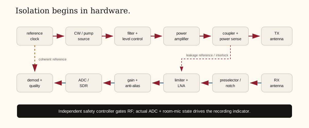
The desired return can be many orders of magnitude below leakage from the reader’s own illumination. The reader architecture therefore needs isolation before software: spatial separation or polarization, filtering, directional coupling/circulation where appropriate, low-phase-noise source, gain staging that cannot saturate, and only then digital cancellation/demodulation.
Frequency-plan gate
Do not treat “ISM” as permission for arbitrary response frequencies or power. In the US, an intentional radiator generally requires FCC certification before marketing, and Part 15 operation must accept interference and not cause harmful interference. RF exposure evaluation also applies to portable equipment. In Europe, the powered reader is radio equipment under the RED; applicable harmonized standards, EMC, safety, spectrum, cybersecurity, and documentation depend on the final architecture and date.
The passive tag may itself be evaluated differently from the powered reader, but the product is sold and operated as a system. Engage a test laboratory before choosing the production band—not after layout.
P1 shielded bench sequence
- Measure the sensor alone: open-circuit voltage spectrum, source impedance, repeatability, and strain limits.
- Measure VSR resonance versus controlled injected sensor voltage with a VNA/fixture.
- Add the PR and characterize both modes, coupling, start threshold, response spectrum, harmonics, and temperature drift.
- Use conducted coupling or a shielded enclosure at minimum practical energy. Record the full spectrum, not only the expected response.
- Apply calibrated audio vibration and recover a known multitone/chirp before speech.
- Freeze the fixture and run component/geometry tolerance sweeps.
Detailed acceptance criteria live in the DVP. Hardware guidance lives in the wearer README and the reader README.